In CNC machining, insufficient surface roughness (e.g., Ra values exceeding design specifications) is typically caused by issues related to cutting tools, cutting parameters, machine tool condition, process design, or post-processing stages. The following presents a systematic solution combining root cause analysis with specific improvement measures:
I. Cutting Tool Optimization
Tool Wear Control
Issue: When tool rake face wear exceeds 0.2mm, the cutting edge becomes dull, causing extrusion rather than cutting. This worsens surface roughness (Ra value increases by 30%-50%).
Solution:
Establish tool life standards: Set replacement thresholds based on material hardness (e.g., for 45# steel, inspect carbide-coated tools every 500 parts processed).
Implement tool wear monitoring systems: Use power sensors or acoustic emission sensors to track cutting force changes in real time, triggering automatic shutdown and tool change when wear exceeds limits.
Select coated tools: For aluminum alloy machining, use TiAlN-coated tools to reduce built-up edge formation and lower Ra values below 0.8 μm.
Tool Geometric Parameter Matching
Issue: Excessive main rake angle concentrates cutting forces, causing surface vibration marks; insufficient front angle increases cutting deformation and worsens roughness.
Solutions:
Optimize main rake angle: Use 45° main rake angle tools for flat machining to distribute cutting forces and reduce vibration.
Adjust front angle and edge inclination: Increase front angle to 15°-20° during finishing, with edge inclination set to -5° for smoother cutting.
Incorporate a finishing edge: Adding a 0.1-0.2mm wide finishing edge to the insert reduces Ra values to 0.4μm.
II. Cutting Parameter Optimization
Feed Rate and Cutting Speed Matching
Issue: Excessive feed increases per-tooth cutting thickness, causing surface tearing; low cutting speed accelerates built-up edge formation.
Solutions:
Recommended finishing parameters:
Steel: Cutting speed 120–180 m/min, feed rate 0.08–0.12 mm/r, depth of cut 0.1–0.3 mm.
Aluminum Alloy: Cutting speed 300–600 m/min, feed rate 0.1–0.15 mm/r, negative depth of cut 0.5–1 mm.
Implement Constant Cutting Force Control: Dynamically adjust feed rate via CNC system to maintain consistent cutting thickness per tooth and prevent load fluctuations.
Cutting Fluid Selection and Usage
Issue: Insufficient emulsion concentration (<5%) leads to inadequate cooling, elevated cutting zone temperatures, material softening, and tool sticking.
Solutions:
Oil-based cutting fluids for finishing: Maintain viscosity at 10-15 cSt (40°C) to form a stable lubricating film, reducing friction coefficient below 0.1.
High-Pressure Cooling (HPC) Technology:
Directly inject coolant at 50-100 bar pressure into the cutting zone to effectively cool and flush chips, reducing rework.
Minimum Quantity Lubrication (MQL):
Precise delivery of plant-based lubricants at 0.5-1 ml/h flow rate. Suitable for difficult-to-machine materials (e.g., titanium alloys), reducing Ra values to 0.2 μm.
III. Machine Tool Condition Adjustment
Spindle Dynamic Balancing Correction
Issue: When spindle imbalance exceeds 0.5 g·mm, high-speed rotation generates centrifugal forces causing periodic vibration marks on workpiece surfaces.
Solutions:
Conduct spindle dynamic balancing inspections every 3 months, using a laser balancer to maintain imbalance below 0.1 g·mm.
Avoid critical speeds during spindle operation.
Guide Rail and Lead Screw Preload
Issue: When guide rail clearance exceeds 0.02mm or lead screw backlash exceeds 0.01mm, table movement causes crawling, resulting in surface waviness >0.01mm.
Solution:
Adjust guide rail preload to achieve 0.01-0.02mm clearance. Implement clamp-type guide rail structures to enhance rigidity.
Apply dual-nut preload to ball screws at 10%-15% of axial load capacity to eliminate backlash.

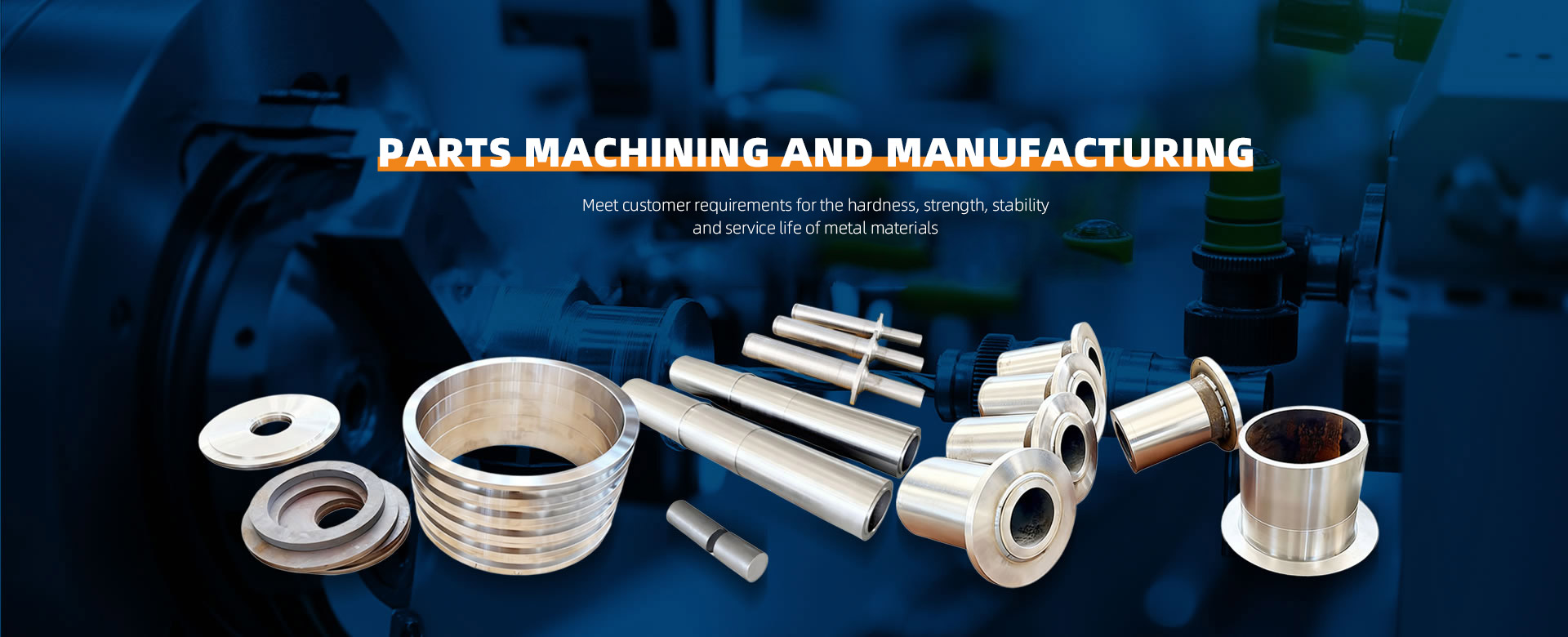
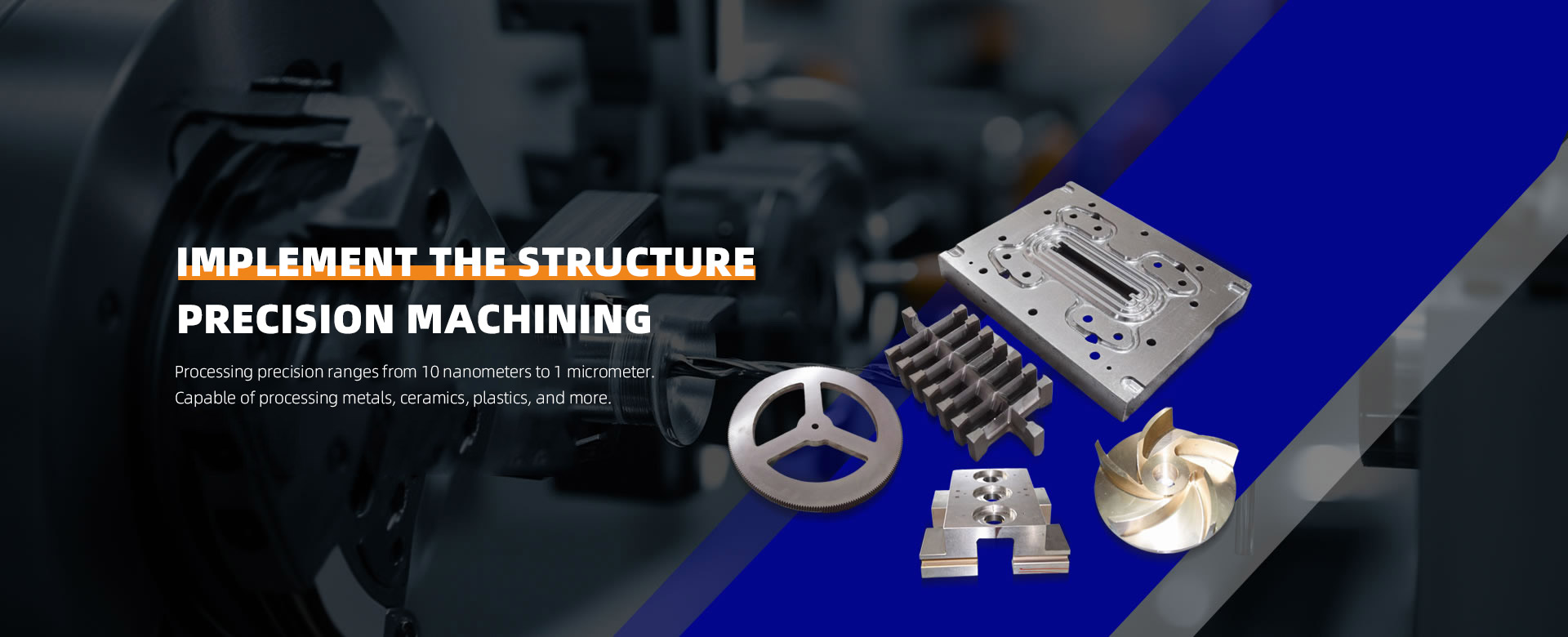
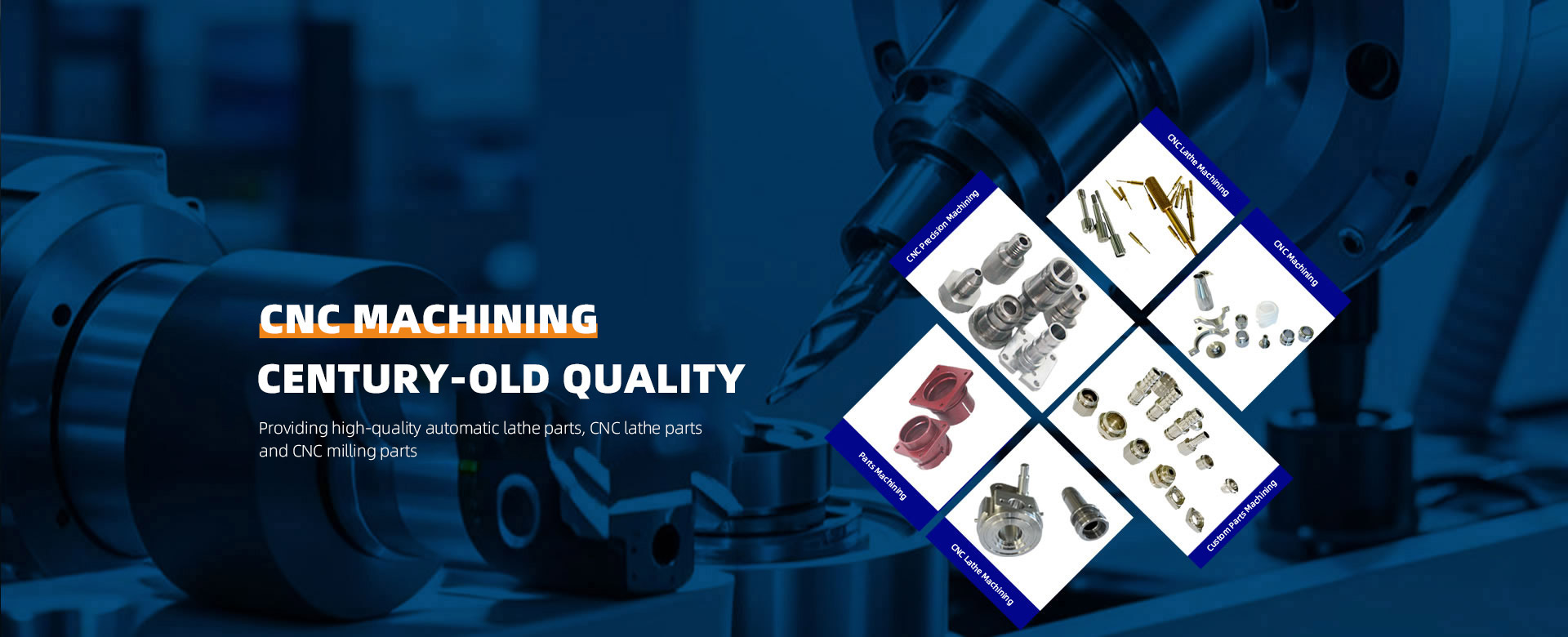
 About ZhenggongZhenggong Electronics (Dongguan) Co., Ltd. is a specialized enterprise dedicated to the precision machining and manufacturing of high-accuracy components.view more
 News CenterFollow Zhenggong Electronics for real-time updates on the latest in high-precision component machining.view more