Machine tool processing (typically CNC machining) often suffers from dimensional instability, a common issue in mechanical manufacturing that can lead to scrap parts or rework. The root causes involve multiple factors including equipment, processes, materials, environment, and operator practices. Below is a detailed analysis and corresponding solutions:
I. Equipment Factors
Degradation of Machine Tool Geometric Accuracy
Guideway Wear: After prolonged use, guideway straightness deviation exceeding 0.02mm/m causes worktable displacement, resulting in systematic dimensional oversize or undersize.
Spindle Radial Runout: Spindle bearing wear or improper assembly causing radial runout >0.005mm may induce hole roundness errors up to 0.01mm.
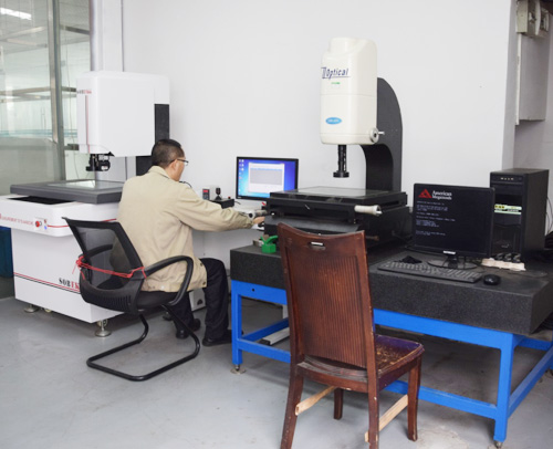
Solution: Periodically inspect machine tool geometric accuracy using a laser interferometer. Conduct major overhauls every six months to replace worn components.
Transmission System Clearances
Ball Screw Backlash: When axial clearance in ball screw assemblies exceeds 0.01mm, reverse positioning errors may cause workpiece dimensional fluctuations. For example, machining stepped shafts may result in periodic diameter overspeeds.
Gear meshing error: When the backlash of transmission gears exceeds 0.03mm, feed rate fluctuations may induce surface waviness, indirectly affecting dimensional accuracy.
Solutions: Adjust the ball screw preload to achieve 0.005-0.01mm clearance, select high-precision gears (Grade 6 or higher), and install encoder feedback compensation.
CNC System Errors
Pulse Equivalent Error: Incorrect servo motor pulse-per-revolution setting (e.g., 8000 pulses/rev instead of 10000 pulses/rev) causes actual movement to deviate from commands.
Interpolation Algorithm Defects: Inaccurate circular interpolation algorithms in some budget CNC systems may produce contour errors exceeding 0.02mm during arc machining.
Solutions: Recalibrate CNC system parameters, upgrade to high-precision interpolation algorithms (e.g., nano-interpolation), or implement closed-loop control systems.
II. Process Factors
Unreasonable Cutting Parameters
Cutting Force Fluctuations: A sudden increase in feed rate from 0.1 mm/r to 0.3 mm/r triples cutting force, potentially causing machine vibration or workpiece elastic deformation, resulting in dimensional deviations.
Cutting Heat Effects: During continuous machining, cutting heat raises local workpiece temperatures by 50°C. Aluminum alloy workpieces may expand by 0.05mm, with subsequent contraction causing dimensional instability.
Solutions: Optimize parameter combinations through cutting trials, e.g., adopt a “constant cutting force” strategy (maintaining constant feed per tooth), and pre-cool the workpiece before machining.
Abnormal Tool Conditions
Tool Wear: When the wear depth on the rear face of a carbide insert exceeds 0.2mm, cutting force increases by 20%, leading to oversized workpieces or worsened surface roughness.
Tool Vibration: When machining with slender tools (length-to-diameter ratio >5) without anti-vibration toolholders, resonance may occur, causing periodic changes in hole diameter.
Solutions: Establish a tool wear database; inspect tool dimensions every 50 parts processed. Use damped vibration-reducing toolholders or adjust spindle speed to avoid resonance zones.
Improper Machining Sequence
Inconsistent Reference Points: Machining internal bores before external surfaces may cause external roundness deviations due to clamping deformation of internal bores.
Heat treatment distortion: Post-quenching dimensional change rate >0.5%. Without machining allowance, final dimensions may become unstable.
Solutions: Follow “surface-first, hole-later; rough-then-finish” principles. Add stabilization processes (e.g., stress-relief annealing) after heat treatment.
III. Material Factors
Poor material homogeneity
Castings Porosity: When aluminum alloy castings have porosity >3%, pitting may appear on the machined surface, causing localized dimensional shortfall.
Steel Segregation: Carbon content deviation in 40Cr steel >0.05% may cause uneven hardness, generating vibration during cutting and affecting dimensional accuracy.
Solutions: Perform ultrasonic testing before machining to detect material defects; select electroslag remelted bars.
Residual Stress Release
Welding Stress: Residual stresses exceeding 200 MPa in welded structural components may cause deformation exceeding 0.1 mm after machining.
Forging Stress: Residual stress release in free-forged parts after machining may result in bending or distortion of the workpiece.
Solutions: Perform stress-relief annealing (hold at 550-650°C for 2 hours) after welding, or apply vibration aging treatment.

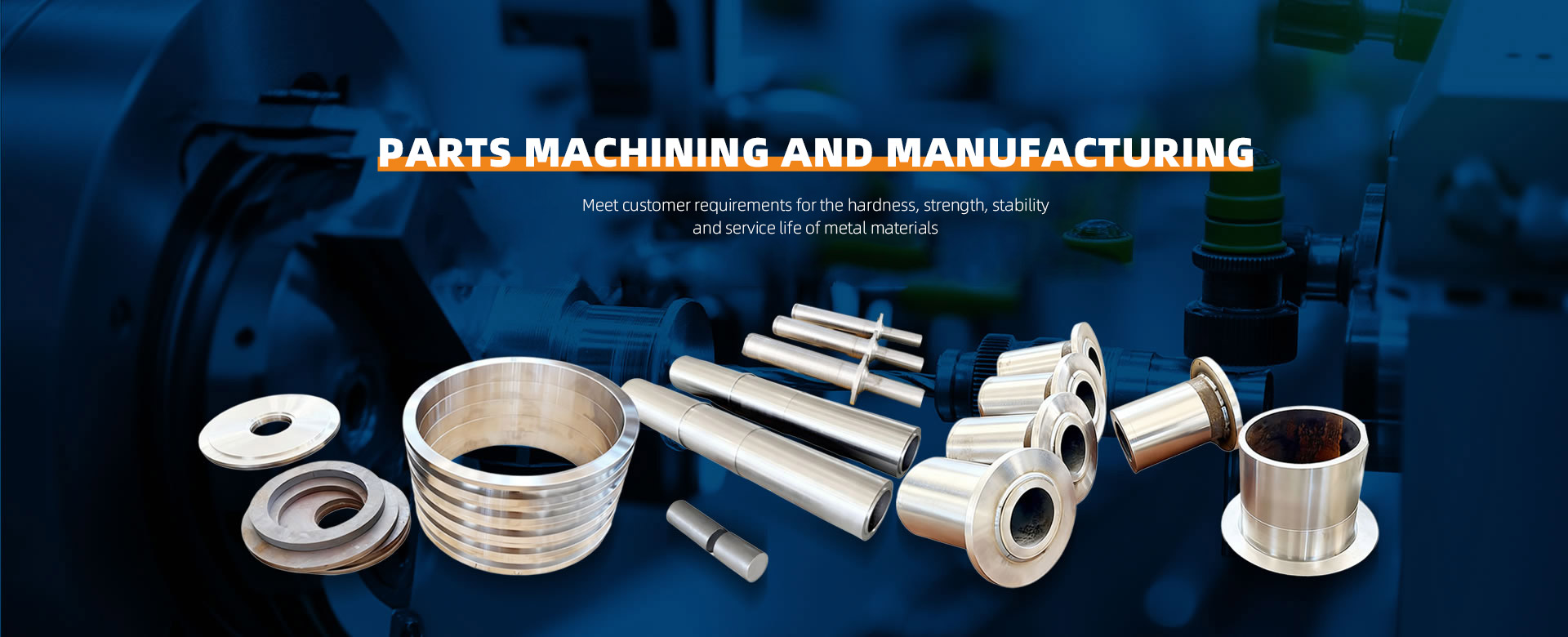
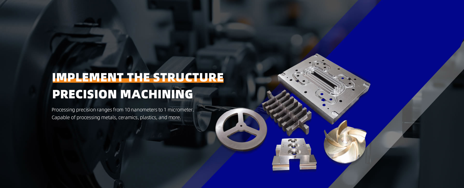
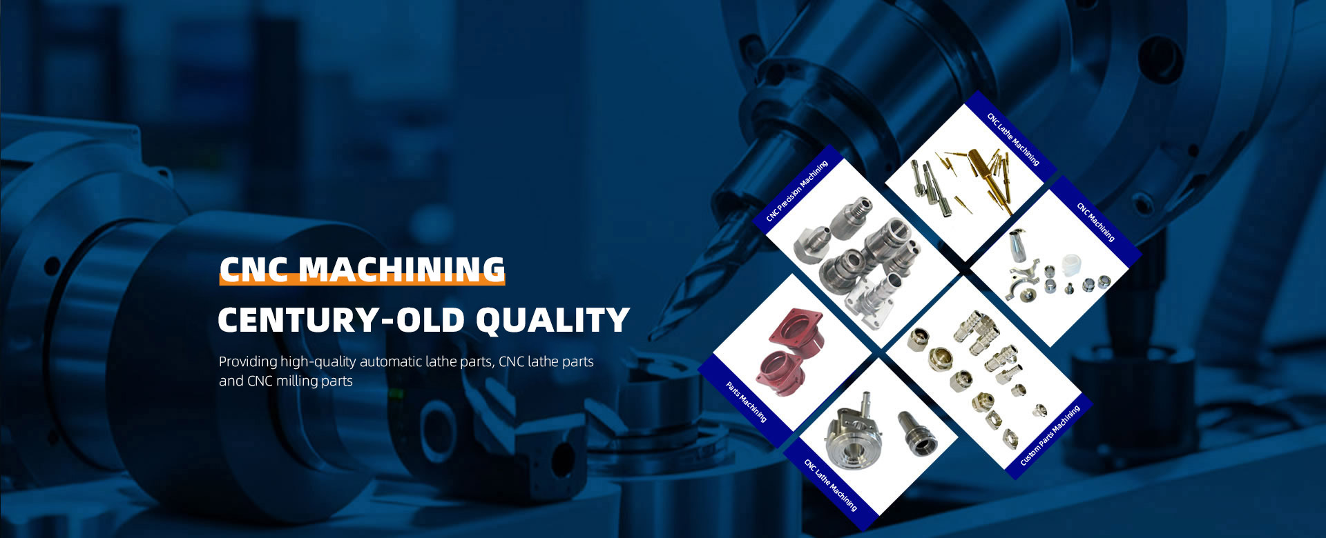
 About ZhenggongZhenggong Electronics (Dongguan) Co., Ltd. is a specialized enterprise dedicated to the precision machining and manufacturing of high-accuracy components.view more
 News CenterFollow Zhenggong Electronics for real-time updates on the latest in high-precision component machining.view more