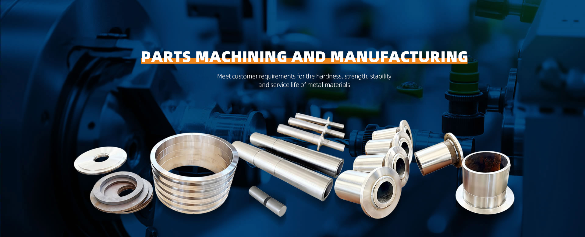
During lathe machining and cutting processes, meticulous attention to detail directly impacts machining accuracy, surface quality, tool life, and operational safety. The following systematically outlines key considerations and practical points across four dimensions: process preparation, machining operations, tool management, and safety precautions:
I. Process Preparation: Ensuring a Solid Foundation
Drawing and Program Review
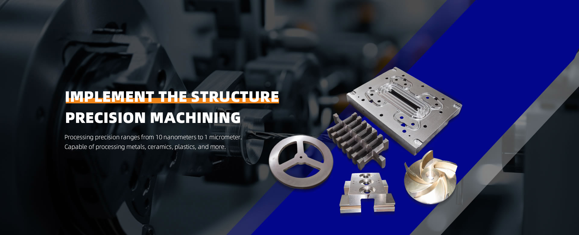
Dimensional Tolerance Verification: Confirm whether part dimensions and geometric tolerances (e.g., roundness, concentricity) fall within the lathe's machining capabilities (e.g., conventional lathes typically have roundness errors ≤0.02mm, while CNC lathes can control this to ≤0.005mm).
Program Simulation Verification: For CNC lathes, simulate machining paths via CAM software to detect overcutting or collision risks (e.g., tool interference with chuck or tailstock).
Process Route Planning: Define cutting parameters (e.g., depth of cut, feed rate) for roughing, semi-finishing, and finishing operations to prevent excessive single-pass cutting that causes vibration or deformation.
Workpiece Clamping Optimization
Fixture Selection:
Three-jaw chuck: Suitable for circular workpieces. Verify jaw concentricity (error ≤0.05mm).
Four-jaw single-action chuck: Used for irregular or eccentric workpieces. Adjust each jaw individually to ensure workpiece center aligns with spindle axis.
Center-mounted clamping: For long shaft-type workpieces, employ single-clamp-single-center or dual-center methods to minimize vibration.
Clamping Force Control:
Use a torque wrench to regulate chuck clamping force (e.g., ≤50 N·m for aluminum alloy parts, ≤100 N·m for steel parts) to prevent deformation or damage.
Auxiliary Support:
For thin-walled components or slender shafts, employ center supports or tool followers to enhance rigidity.
Tool Presetting and Tool Setting
Tool Installation:
Check for loose insert locking screws to prevent insert detachment during machining.
Ensure tool tip radius compensation values (e.g., R0.4mm, R0.8mm) match the program specifications.
Tool Setting Accuracy:
When manually setting tools, use trial cutting to measure the workpiece coordinate system, with errors controlled within ±0.02mm.
CNC lathes should utilize tool setters to enhance efficiency and precision.
Tool Wear Monitoring: Inspect insert rake angle and main cutting angle for wear before machining (e.g., check carbide inserts once per shift).
II. Machining Operations: Precise Control of the Cutting Process
Cutting Parameter Selection
Depth of Cut (ap):
Roughing: 2-5mm for steel, 3-6mm for cast iron.
Finishing: ≤0.5mm to prevent vibration caused by excessive cutting forces.
Feed Rate (f):
Roughing: 0.1-0.3mm/r (steel), 0.05-0.15mm/r (aluminum alloy).
Finishing: 0.05-0.1mm/r to ensure surface roughness (Ra ≤ 1.6μm).
Spindle Speed (n):
Adjust based on material hardness (e.g., n=500-800 r/min for rough machining of 45# steel, n=1000-1500 r/min for finish machining).
Avoid built-up edge formation during high-speed cutting (e.g., recommended cutting speed ≤300 m/min for aluminum alloys).
Cutting Fluid Usage
Type Selection:
Emulsions: General-purpose, suitable for steel and cast iron (concentration 5%-10%).
Synthetic Cutting Fluids: Environmentally friendly, suitable for aluminum alloys and copper alloys.
Cutting Oils: Used for heavy-duty cutting or difficult-to-machine materials (e.g., stainless steel).
Spray Method:
Ensure cutting fluid covers the tool tip and workpiece contact area to prevent localized overheating.
Regularly inspect nozzles for clogging and adjust spray angle (recommended 30°–45° relative to tool).
Process Monitoring
Vibration Detection: Identify vibrations by listening for abnormal sounds or observing chip morphology (e.g., serrated chips may indicate vibration).
Temperature Control: Monitor workpiece surface temperature using a handheld infrared thermometer (recommended ≤80°C) to prevent thermal deformation.
Dimensional Sampling:
Inspect 1 piece per 5-10 processed items using micrometers or calipers to measure critical dimensions.
III. Tool Management: Extending Service Life and Precision
Tool Selection and Matching
Material Compatibility:
Carbide Inserts: Suitable for steel and cast iron (e.g., YG8 for cast iron, YT15 for steel).
Ceramic Inserts: For high-speed cutting of hard materials (e.g., hardened steel).
Diamond inserts: For finishing non-ferrous metals (e.g., copper, aluminum).
Geometric Angles:
Rake angle (γ): Increasing rake angle reduces cutting forces (e.g., 15°-25° for aluminum alloy machining).
Clearance angle (α): Use 8°-12° during finishing to minimize friction.
Tool Replacement Criteria
Wear Limit:
Replace when rear face wear VB ≥ 0.3mm.
Replace immediately if chipping or crescent-shaped wear appears on the cutting edge.
Tool Change Procedure:
After stopping the machine, disconnect power and replace the insert using a dedicated wrench.
Perform tool re-calibration after replacement to prevent coordinate errors.
Tool Storage and Maintenance
Rust Prevention: Clean tools after use, apply rust-preventive oil, and store in a dry cabinet.
Categorized Management: Store tools by blade type and specification to prevent cross-use.
Regular Calibration: Inspect tool holder taper wear monthly (e.g., contact area for 7:24 taper shanks must be ≥80%).

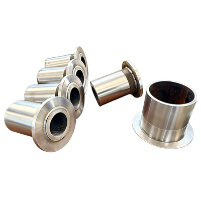
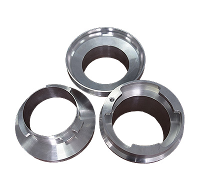
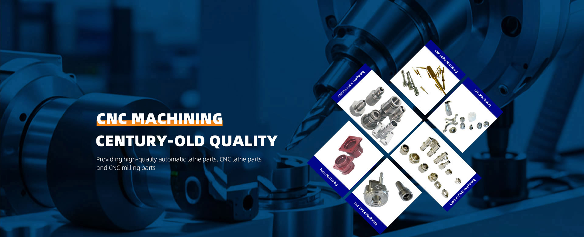
 About ZhenggongZhenggong Electronics (Dongguan) Co., Ltd. is a specialized enterprise dedicated to the precision machining and manufacturing of high-accuracy components.view more
 News CenterFollow Zhenggong Electronics for real-time updates on the latest in high-precision component machining.view more