After lathe machining is completed, quality inspection is a critical step to ensure products meet design requirements. Inspection must cover multiple dimensions including dimensional accuracy, geometric accuracy, surface quality, and functional characteristics, utilizing scientific methods and tools. Below is the detailed process and key points for lathe machining quality inspection:
I. Pre-inspection Preparation
Define Inspection Standards
Determine critical requirements based on drawings, technical agreements, or industry standards (e.g., ISO, GB), including dimensional tolerances (e.g., ±0.01mm), geometric tolerances (e.g., roundness ≤0.005mm), and surface roughness (e.g., Ra≤0.8μm).
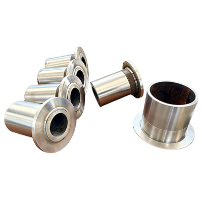
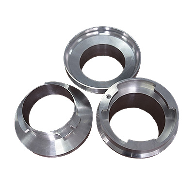
Example: Shaft components require inspection of diameter, length, and radial runout; hole components require inspection of bore diameter, cylindricity, and coaxiality.
Select Inspection Tools
General-purpose gauges: Calipers (accuracy 0.02mm), micrometers (accuracy 0.001mm), dial indicators (accuracy 0.01mm).
Specialized Gauges: Thread gauges (for pitch/flank angle inspection), plug gauges (for hole diameter pass/fail inspection), ring gauges (for shaft diameter pass/fail inspection).
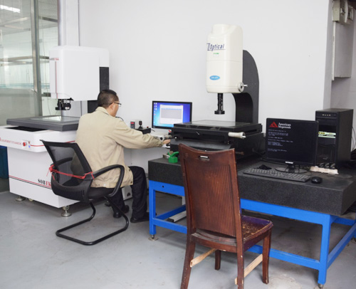
Coordinate Measuring Machine (CMM): Suitable for complex surfaces or high-precision geometric tolerance inspection (accuracy up to 0.001mm).
Surface Roughness Tester: Stylus-type or optical-type, measures Ra and Rz values.
Image Measuring System: Non-contact 2D dimensional inspection, suitable for small batches or precision components.
Workpiece Cleaning
Remove burrs, chips, and oil residues to prevent measurement errors. Examples: Use compressed air to blow out debris from holes, or clean surfaces with an ultrasonic cleaner.
II. Core Inspection Items and Methods
1. Dimensional Accuracy Inspection
Shaft Diameter:
Method: Measure at three evenly spaced axial positions using an outside micrometer, taking the average value.
Note: Avoid excessive measurement force causing part deformation. Micrometers must be calibrated with zero error ≤0.002mm.
Bore Diameter:
Method: Inspect using an inside micrometer or coordinate measuring machine (CMM). Measurements must be taken at three distinct levels—top, middle, and bottom—along the bore depth.
Example: When inspecting a φ50H7 bore, if the CMM result is φ50.012mm, exceeding the tolerance zone (+0.021mm, +0.000mm), the part is deemed non-conforming.
2. Geometric Tolerance Inspection
Roundness/Cylindricity:
Method: Measure 8-12 equidistant cross-sections along the circumference using a roundness gauge (accuracy 0.1μm) or CMM.
Standard: Roundness error ≤ 50% of tolerance value (e.g., if tolerance is 0.01mm, actual error must ≤ 0.005mm).
Coaxiality:
Method: Clamp the workpiece in a V-block and measure axial runout with a dial indicator, or establish a reference axis via CMM and calculate deviation.
Example: When inspecting coaxiality between two shafts, a CMM result of 0.02 mm (tolerance 0.01 mm) requires rework or scrap.
3. Surface Quality Inspection
Surface Roughness:
Method: Measure using a stylus roughness tester along the machining direction, taking the average of 3 different positions.
Standard: Select Ra value per design requirements (e.g., finished surfaces Ra ≤ 0.8μm, rough surfaces Ra ≤ 3.2μm).
Optimization: If Ra exceeds specifications, reduce via post-processing like polishing or electrolytic polishing.
Surface Defects:
Method: Visual inspection (with magnifier) or fluorescent penetrant testing (for micro-defects like cracks/pores).
Example: Scratches >0.5mm on aluminum alloy parts require rework or downgraded use.
4. Thread Inspection
Pitch/Thread Angle:
Method: Measure using thread gauges or a thread microscope, inspecting pitch deviation on 3-5 threads.
Standard: Pitch deviation ≤ 60% of tolerance value (e.g., for M10×1.5 thread with ±0.1mm tolerance, actual deviation must be ≤ ±0.06mm).
Mean Diameter/Minimum Diameter:
Method: Inspect pass/fail using thread plug gauges (for holes) or ring gauges (for shafts). Pass gauges must pass, while fail gauges must not pass.
Example: When inspecting an M12 thread ring gauge, if the go gauge cannot be screwed in, it indicates the mean diameter is too small, requiring adjustment of the lathe tool's radial dimensions.
III. Functional and Special Inspections
Fit Inspection
Method: Test-fit the machined part with mating components (e.g., bearings, gears) to check clearance and rotational flexibility.
Standard: Press-fit interference must meet design range (e.g., φ50H7/p6 fit requires 500-800N press force).
Hardness Testing
Method: Measure three random points on the workpiece surface using a Rockwell hardness tester (HRC) or Vickers hardness tester (HV).
Standard: Select hardness range based on material (e.g., quenched and tempered 45# steel requires 220-250 HBW).
Balancing Inspection
Applicable Components: Rotating parts (e.g., motor shafts, flywheels).
Method: Dynamic balancing machine inspection. Unbalance must be ≤ design requirements (e.g., Grade G1 allows unbalance e=1 mm/kg).

 About ZhenggongZhenggong Electronics (Dongguan) Co., Ltd. is a specialized enterprise dedicated to the precision machining and manufacturing of high-accuracy components.view more
 News CenterFollow Zhenggong Electronics for real-time updates on the latest in high-precision component machining.view more