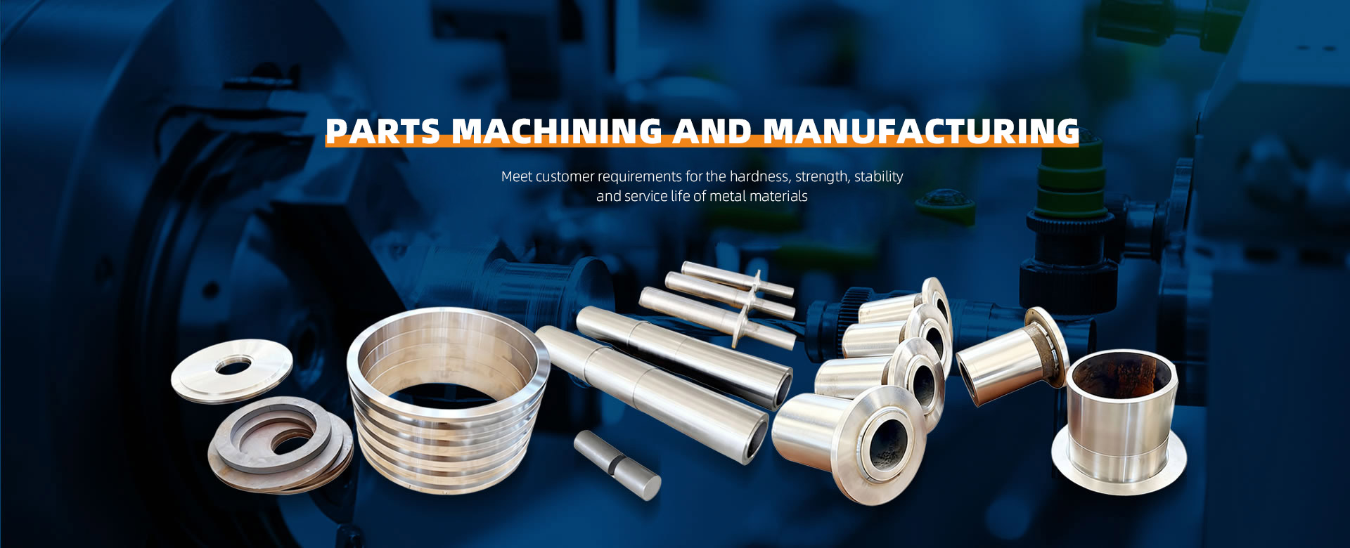
During lathe machining, operational details must be strictly controlled across four core dimensions: safety precautions, equipment preparation, machining operations, and quality monitoring. Key points are as follows:
I. Safety Precautions: Mitigating Personnel and Equipment Risks
Personal Protective Equipment (PPE)
Wearing Requirements: Before operation, wear tight-sleeved work clothes and safety shoes; wear protective goggles and a work cap. Female operators must tie back hair and wear work caps. Gloves, scarves, ties, or loose clothing are strictly prohibited to prevent entanglement in rotating components.
Tool Usage:
Use iron hooks or brushes to clear chips; never touch chips with bare hands. When finishing workpieces with files, position the right hand forward and left hand backward. Use a “hand-held clamp” tool for sandpaper grinding to prevent crushing injuries.
Equipment Safety Inspection
Pre-startup Verification: Ensure chuck wrench is removed, guards are in place, and lubrication system functions normally. Conduct a 5-minute manual test run before startup to confirm no abnormalities.
Prohibited During Operation: Do not measure workpieces, adjust tools, or remove fixtures while the lathe is running. Do not pass items across the lathe to prevent collisions.
Post-Shutdown Procedures: Wait for the spindle to come to a complete stop after powering off before removing workpieces or clearing chips. Apply rust-preventive oil when cleaning guideways to prevent corrosion.
II. Equipment Preparation: Ensuring a Stable Machining Foundation
Tool Management
Selection and Installation: Choose tools based on material (e.g., carbide inserts for steel, ceramic inserts for hardened steel). Ensure tool tips align with the spindle centerline (height tolerance ≤0.5mm).
Test Cutting Verification: Perform test cuts for each new tool or after regrinding to verify actual length matches tool offset values. When setting non-reference tools, record gauge readings and input them into the system.
Wear Monitoring: Replace inserts when rear face wear (VB) reaches ≥0.3mm. Immediately halt operation for chipped cutting edges or crescent-shaped wear.
Workpiece Clamping
Fixture Selection: Use three-jaw chucks for round workpieces and four-jaw chucks for irregular shapes. Support slender shafts with centers + tool followers to prevent vibration.
Clamping Force Control: Adjust chuck clamping force using a torque wrench (e.g., ≤50 N·m for aluminum alloy workpieces, ≤100 N·m for steel parts) to prevent deformation.
Balance Correction: After clamping, gently tap the workpiece with a wooden mallet to correct balance. Ensure cylindrical protrusion from the chuck does not exceed three times the diameter to prevent excessive centrifugal force.
Programming and Coordinate System Setup
Program Verification: Validate toolpaths via graphical simulation on the CNC lathe to ensure collision-free operation. After manual program input, verify code, commands, and syntax.
Coordinate System Setup: Set the origin at the center of the workpiece's right end face (G54). Determine X0 during trial cutting of the outer diameter and Z0 during end face contact. Verify settings after inputting into the system.
III. Machining Operations: Precise Control of the Cutting Process
Cutting Parameter Selection
Roughing: For steel parts, use a depth of cut of 2-5mm, feed rate of 0.1-0.3mm/r, and spindle speed of 500-800r/min. For cast iron, use a depth of cut of 3-6mm and feed rate of 0.05-0.15mm/r.
Finishing: Depth of cut ≤0.5mm, feed rate 0.05-0.1mm/r, spindle speed 1000-1500r/min, ensuring surface roughness Ra≤1.6μm.
Material Adaptation:
Recommended cutting speed for aluminum alloys ≤300m/min to prevent built-up edge;
Ceramic inserts required for quenched steel to reduce cutting forces.
Cutting Fluid Usage
Type Matching:
Emulsions for steel and cast iron (5%-10% concentration);
Synthetic cutting fluids for aluminum and copper alloys;
Cutting oils for heavy-duty machining.
Spray Control: Adjust nozzle angle (30°-45° relative to tool) to ensure coolant coverage over tool tip and workpiece contact zone, preventing localized overheating.
Process Monitoring
Vibration Detection: Listen for abnormal sounds or observe chip morphology (e.g., serrated chips indicate vibration). Adjust feed rate or cutting depth accordingly.
Temperature Control: Monitor workpiece surface temperature using a handheld infrared thermometer (recommended ≤80°C) to prevent thermal deformation.
Dimension Sampling: Inspect 1 piece per 5-10 processed items. Measure critical dimensions with a micrometer or caliper to ensure tolerance compliance.

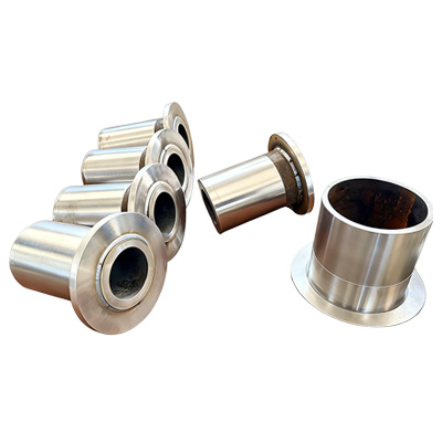
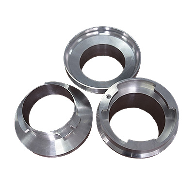
 About ZhenggongZhenggong Electronics (Dongguan) Co., Ltd. is a specialized enterprise dedicated to the precision machining and manufacturing of high-accuracy components.view more
 News CenterFollow Zhenggong Electronics for real-time updates on the latest in high-precision component machining.view more