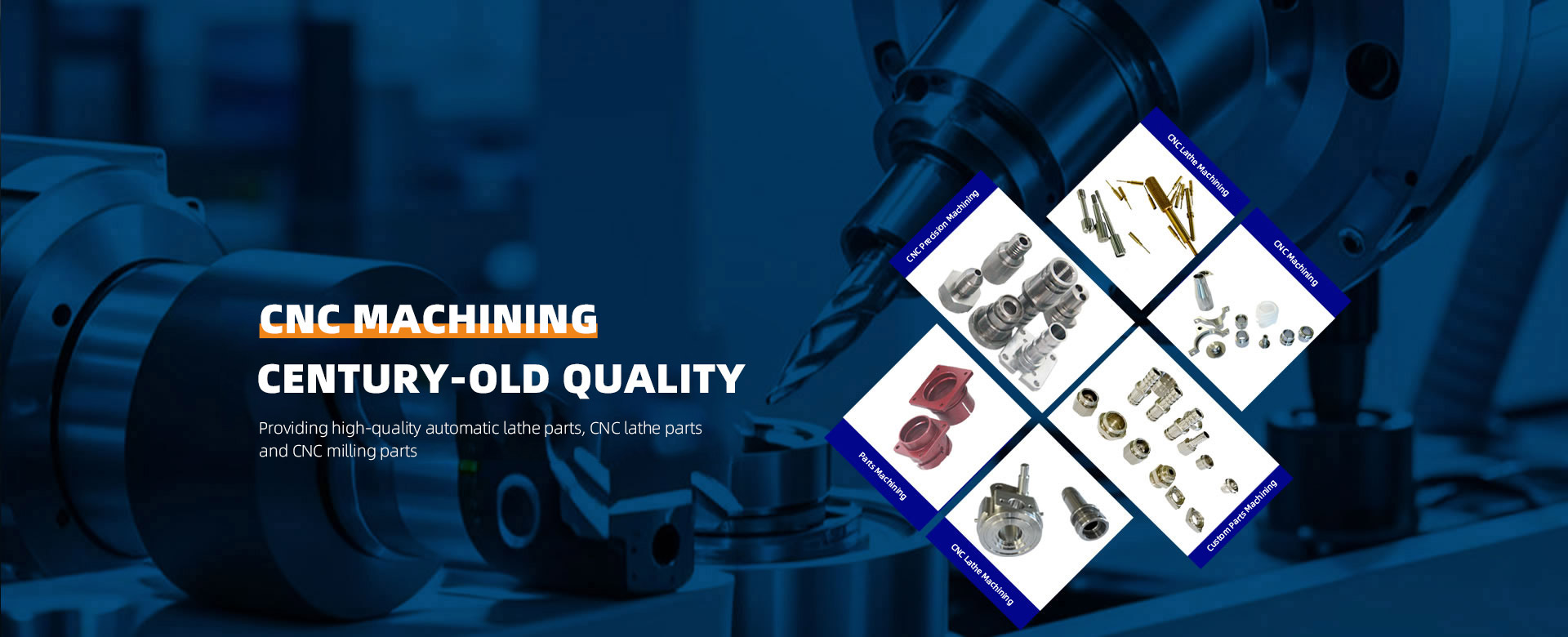
CNC machining (Computer Numerical Control machining) achieves automated, high-precision part manufacturing by precisely controlling machine tool movements and cutting parameters through computer programs. Its workflow encompasses five core stages: design, programming, machine setup, machining execution, and post-processing. Below is a detailed breakdown:
I. Design Phase: From Drawings to Digital Models
CAD Modeling
Design three-dimensional models of parts using software such as SolidWorks or AutoCAD, defining dimensions, shapes, and tolerance requirements.
For example, designing an aircraft engine blade requires precise modeling of its complex surfaces and streamlined structure.
CAM Programming
Convert the 3D model into machine-readable G-code (CNC programs) using CAM software like Mastercam or UG.
The program includes parameters such as tool paths, spindle speed, feed rate, and cutting depth. For example, rough machining might set a cutting depth of 2mm and a feed rate of 500mm/min; finishing operations reduce the cutting depth to 0.1mm and the feed rate to 200mm/min.
II. Machine Setup: Hardware and Software Coordination
Workpiece Clamping
Select fixtures (e.g., three-jaw chucks, vise clamps, or vacuum suction cups) based on part geometry to ensure secure workpiece fixation and meet positioning accuracy requirements.
For instance, specialized fixtures are required to prevent deformation when machining smartphone midframes.
Tool Selection and Installation
Select tool type (e.g., carbide end mills, ceramic tools) and dimensions (e.g., 6mm diameter end mills) based on material hardness and machining requirements.
Mount tools onto the spindle and adjust using a dynamic balancer to minimize vibration.
Program Input and Debugging
Transfer G-code to the machine control system (e.g., FANUC, Siemens) via USB drive, network, or DNC (Direct Numerical Control).
Verify the program in simulation software or conduct trial runs on the machine to check for collision risks. For example, use VERICUT software to simulate the machining process and identify tool overcutting or interference issues in advance.
III. Machining Execution: Automation and Precision Control
Machine Initialization
Return the machine to zero (reference point) to establish the coordinate origin.
Input the workpiece coordinate system offset values to ensure the coordinates in the program match the actual workpiece position.
Automatic Machining Sequence
Roughing: Rapidly remove bulk material, leaving a uniform allowance (typically 0.5–1 mm) for subsequent finishing.
Semi-finishing: Further reduce material allowance while correcting geometric errors.
Finishing: Achieve final dimensions and surface quality with micron-level precision. For example, when machining mold cavities, surface roughness must reach below Ra 0.8 μm during finishing.
Real-Time Monitoring and Adjustment
Sensors monitor cutting force, temperature, vibration, and other parameters. The control system automatically adjusts feed rate or spindle speed based on feedback.
IV. Key Technology Support: Achieving High Precision and Efficiency
Multi-Axis Interpolation Technology
Five-axis CNC machines achieve efficient machining of complex surfaces through the coordinated movement of rotary axes (A/B/C axes) and linear axes (X/Y/Z axes).
High-Speed Cutting Technology (HSC)
Spindle speeds reach 10,000–30,000 rpm, with feed rates exceeding 10 m/min, significantly reducing processing time.
Ideal for machining lightweight materials like aluminum and magnesium alloys, such as rapid prototyping of laptop casings.
Closed-Loop Feedback System
Sensors like linear scales and encoders monitor tool position in real time, with the control system correcting errors via closed-loop algorithms.
V. Post-Processing: Quality Inspection & Surface Treatment
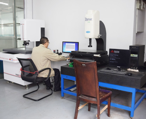
Dimensional Inspection
Critical dimensions are verified using coordinate measuring machines (CMMs), or geometric tolerance analysis is performed via laser scanners.
Surface Treatment
Perform polishing, sandblasting, anodizing, or chrome plating as required to enhance surface quality and corrosion resistance.
Deburring and Cleaning
Remove burrs from machined edges using manual or automated deburring equipment to prevent scratches or assembly interference.
Utilize ultrasonic cleaning machines to eliminate cutting fluids and metal chips, ensuring part cleanliness.

 About ZhenggongZhenggong Electronics (Dongguan) Co., Ltd. is a specialized enterprise dedicated to the precision machining and manufacturing of high-accuracy components.view more
 News CenterFollow Zhenggong Electronics for real-time updates on the latest in high-precision component machining.view more